


Secondary circuit of the switchgear
Secondary circuit of the switch cabinet
1. Overview of the secondary circuit of the switch cabinet
The main components of the switch cabinet include: vacuum circuit breaker, current transformer, locally installed microcomputer protection device, operating circuit accessories (handles, indicator lights, pressure plates, etc.), and various position auxiliary switches. Among them, the circuit breaker and current transformer are installed inside the switch cabinet, while the microcomputer protection, accessories, and electric meters are installed on the panel of the relay room (continuing the previous terminology, although there are actually no relays anymore). The terminal block and various power air switches are installed inside the relay room, and the terminal block is connected to the circuit breaker mechanism via control cables or dedicated sockets.
To understand the secondary wiring of the switch cabinet, we need to find two sets of drawings: the protection schematic and wiring diagram provided by the microcomputer protection manufacturer; the secondary schematic, wiring diagram, terminal block diagram, and circuit breaker mechanism schematic provided by the switch cabinet manufacturer.
The documentation from the protection manufacturer serves as the original design basis for the switch cabinet manufacturer and is also the basis for our review of the switch cabinet manufacturer's drawings. The schematic from the switch cabinet factory is generally modified based on the microcomputer protection schematic, and it illustrates the input of current, voltage, and signal quantities, as well as the output of control quantities.
Subscription Information
We will send you real-time information regularly!

Specializing in electric power engineering construction, electrical products production and sales
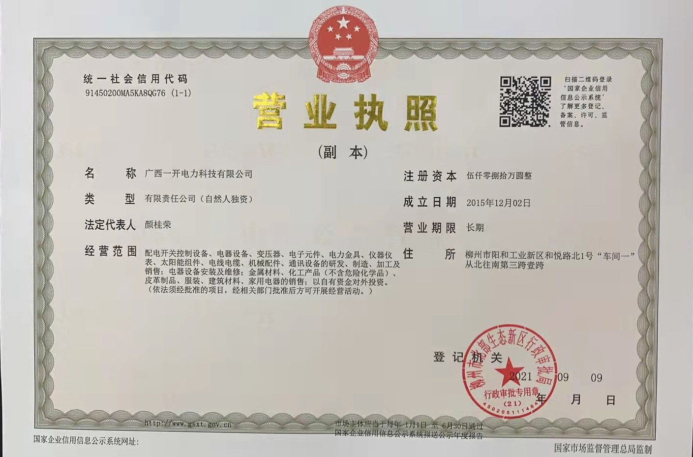
Guangxi Yikai Electric Power Technology Co., Ltd.
Address: Building B03, No.10 Panyun Road, Liubei District, Liuzhou City, Guangxi Zhuang Autonomous Region
web
All rights reserved©2024 Guangxi Yikai Electric Power Technology Co., Ltd.